Three engineering students in Biola's Summer Engineering Internship spent a summer in the kinematic equations behind double wishbone suspension, producing the validated parameter set Biola's Baja SAE team will fabricate.
Before Biola Racing machines a single part for its Baja SAE vehicle, someone has to prove the suspension geometry is right. Machine a part around the wrong parameters and the vehicle bottoms out on rough terrain, loses tire contact in corners, or steers unpredictably when the chassis rolls into a turn. The proof comes first.
Three students in Biola University's Summer Engineering Internship (SEI) 2026 ran that proof. Ho Hei Ng, Emilio Ramirez, and Lincoln Tenney spent the summer working through the suspension literature, selecting an architecture, defining target parameters, and building the kinematic model that validates the geometry. Their client was Biola Racing, the university's Society of Automotive Engineers (SAE) collegiate chapter, which competes in Baja SAE, an intercollegiate competition where teams design and build off-road vehicles from scratch. Prof. Todd Curtis served as both client and mentor; Dr. Nathan Cho as SEI mentor. Aran Blazar, CTO of Biola Racing's team, brought the engineering requirements; Matthew Chang supported the project as SEI Worker.
The Racing Problem
Baja SAE courses are designed to break vehicles. Rocks, drops, and high-speed rough sections put suspension under loads that expose every parameter decision the design team made. A ride height set too low bottoms the frame. A roll center placed too high induces jacking, where the body lifts instead of rolling, reducing tire contact and destabilizing the vehicle. Scrub radius set too wide produces unpredictable steering feedback when the wheel changes camber angle through a corner.
"Working through the suspension literature sharpened my skills in engineering design, research, computer-aided design (CAD) modeling, and systems thinking," said Ramirez. "I am incredibly grateful to Dr. Nathan Cho, Professor Todd Curtis, and Matthew Chang for their outstanding mentorship. Their guidance challenged me to think more critically and approach problems as an engineer."
Double Wishbone
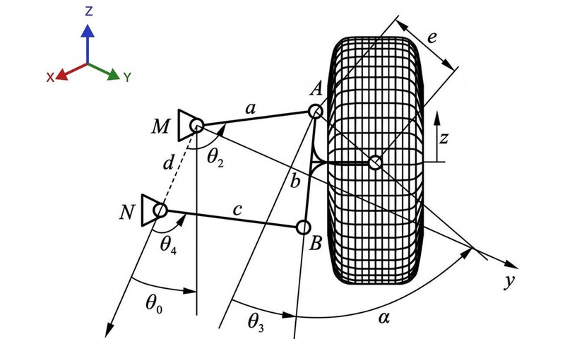
The team evaluated two architectures: MacPherson Strut and Double Wishbone. MacPherson is common in production vehicles and simpler to package, but it limits how much camber angle can be tuned across the suspension's range of travel. Double Wishbone was selected on four counts: tunable camber gain through full travel, better tire contact in turns and on straights, resilience under hard cornering loads, and simplified kinematic behavior through restricted degrees of freedom.
The validated parameter targets: scrub radius approximately zero, to minimize steering kickback; caster angle greater than zero, for straight-line stability and returnability; camber angle less than zero, to load the outside tire in corners; ride height 12 to 18 inches; roll center at 0.3 to 0.5 times the center of gravity height; front suspension travel 10 to 12 inches; rear travel 12 to 14 inches.
Six Degrees of Freedom
With the architecture and parameters set, the team built a six-degree-of-freedom (DOF) kinematic model to verify that the geometry behaves correctly through the suspension's full range of motion. In suspension terms, six DOF means the model tracks every independent way the wheel assembly can move: up and down, fore and aft, laterally, and rotationally in all three axes. The key output was camber angle variation through travel, defined as the difference between the instantaneous and static camber angles, a function of how far the coupler point moves vertically as the suspension compresses. The model checked performance under two conditions: roll, the lean that happens when the vehicle corners, and bump, the vertical deflection when a wheel hits terrain. A geometry that holds camber through both keeps the tire flat on the ground regardless of what the course demands.
What Comes Next
The literature review and kinematic analysis are the first of four stages. Iterative kinematic optimization will refine the hard point locations; from there, CAD assembly translates those points into a physical model, finite element analysis (FEA) tests the load-bearing components, and integration mounts the completed suspension onto the full Baja vehicle. The parameter set the SEI team produced drives every subsequent stage.